Article type: Technical guidance / how-to
Service focus: Ontario Site Servicing & Stormwater
Primary keyword: stormwater management reports Ontario
Constrained infill and redevelopment sites across Ontario rarely have space for a traditional stormwater management pond. Buildings, parking areas, property lines, existing services, neighbouring properties, and municipal right-of-way constraints often leave only a small area for stormwater controls.
A properly prepared stormwater management report in Ontario must therefore combine clear calculations with practical controls. The design must control runoff, protect adjacent properties, meet municipal criteria, and fit within a coordinated civil design.
Reliance Engineering prepares stormwater management reports, site servicing plans, and functional servicing reports for development and redevelopment projects across Ontario.
Start With the Approval Criteria
There is no single province-wide allowable release rate that applies to every site. The controlling criteria may come from:
- The local municipality
- A regional municipality or county
- A watershed or subwatershed study
- An approved master servicing strategy
- The receiving storm sewer capacity
- A Conservation Authority
- A previous approval or site-specific engineering condition
The first step is to confirm the criteria before selecting a storage system or outlet. Pre-consultation with the municipality and, where relevant, the Conservation Authority can identify requirements for:
- Allowable release rates
- Required storm events
- Water quality treatment
- Erosion control
- Water balance and infiltration
- Storm connection details
- Floodplain and regulated-area limits
- Emergency overland flow routes
- Operation and maintenance responsibilities
Site plan control allows municipalities to review and regulate site drainage, grading, servicing, and related technical matters. A stormwater strategy must therefore support the complete municipal approvals process, not operate as a separate calculation package.
Compare Pre- and Post-Development Drainage
A constrained site should be evaluated in both its existing and proposed conditions.
The pre-development analysis should identify:
- Existing drainage areas
- Existing surface types
- Existing catchbasins and storm connections
- Existing overland flow routes
- Runoff directed to adjacent properties or rights-of-way
- Existing municipal or private storm infrastructure
The post-development analysis should show how the proposed building, pavement, landscape areas, roof drainage, storage systems, and storm connection change the drainage pattern.
Runoff coefficients are typically assigned to each surface type. Roofs and paved areas have higher runoff coefficients than landscaped areas. The weighted runoff coefficient can be calculated as:
[
C_w = \frac{\sum(C_i A_i)}{\sum A_i}
]
Where:
- (C_w) is the weighted runoff coefficient
- (C_i) is the runoff coefficient for each surface
- (A_i) is the area of each surface
For smaller drainage areas, the Rational Method may be used where accepted by the municipality:
[
Q = 0.00278CIA
]
Where:
- (Q) is peak flow in cubic metres per second
- (C) is the runoff coefficient
- (I) is rainfall intensity in millimetres per hour
- (A) is the drainage area in hectares
The selected rainfall data, time of concentration, design storms, and modelling method must match the applicable municipal criteria. A clear pre-development, post-development, and controlled-flow table helps reviewers understand the design quickly.
Calculate the Allowable Release Rate
The allowable release rate is commonly based on the lesser of:
- The pre-development peak flow
- A watershed or master-plan target
- The capacity of the receiving storm sewer
- A specific municipal unit-area release rate
- A site-specific condition from the approval authority
The target may apply to several storm events, not only one. Municipalities may require review of the 2-year, 5-year, 10-year, 25-year, 50-year, and 100-year events. Some sites also require downstream hydraulic review.
The report should clearly identify:
- The uncontrolled post-development peak flow
- The required controlled release rate
- The difference between uncontrolled flow and allowable flow
- The storage volume required to control the difference
- The controlled discharge for each required storm event
The Ontario Stormwater Management Planning and Design Manual recognizes that infill sites may require quantity controls because of sewer capacity, local flooding, and downstream impacts. It also identifies compact approaches such as rooftop storage, underground systems, parking area storage, and distributed source controls.
Design Storage for Tight Sites
A constrained site may use one or several of the following controls:
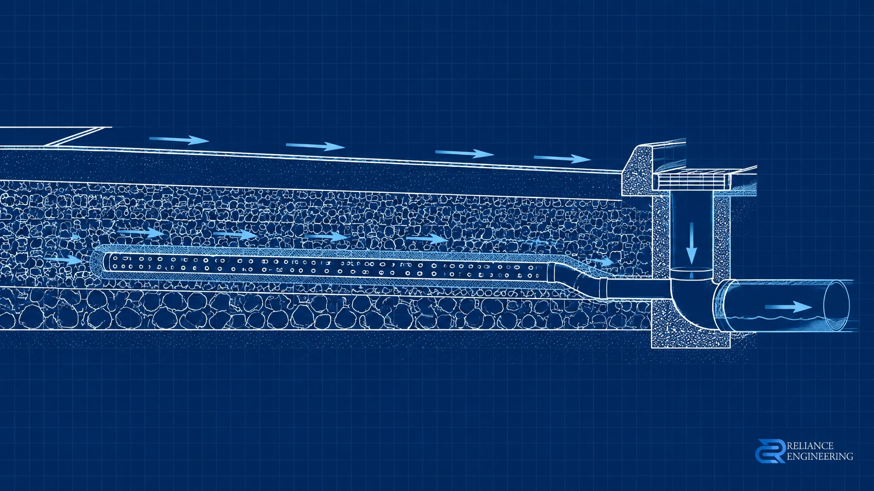
- Underground detention chambers
- Oversized storm pipes or superpipes
- Stormwater tanks
- Controlled rooftop drainage
- Parking lot or courtyard depression storage
- Bioretention and infiltration systems
- Small dry storage areas
- Distributed source controls
Storage design should not rely on a simple volume estimate alone. The report should provide a stage-storage-discharge relationship that demonstrates how water enters, is stored, and is released over time.
For underground storage, the design should show:
- Chamber or tank dimensions
- Storage volume
- Access points
- Maintenance clearances
- Inlet and outlet elevations
- Inspection ports
- Sediment management provisions
- Emergency overflow
- Connection to the receiving storm system
If surface storage is used in a parking area or landscaped depression, the design should identify maximum ponding depth, ponding limits, surface elevations, and safe overflow routing. The grading plan must confirm that water will not enter buildings or flow onto neighbouring properties.

Size the Orifice and Outlet Control
The outlet control determines whether the storage system meets the allowable release rate. A preliminary circular orifice check may use:
[
Q = C_d A\sqrt{2gH}
]
Where:
- (Q) is discharge
- (C_d) is the discharge coefficient
- (A) is the orifice area
- (g) is gravitational acceleration
- (H) is the hydraulic head measured to the orifice centreline
The final design should evaluate the outlet across the full range of water levels. It should also consider:
- Tailwater conditions
- Downstream storm pipe capacity
- Orifice submergence
- Drawdown time
- Debris and sediment
- Access for inspection
- Emergency overflow conditions
- Maintenance responsibility
Very small orifices can clog if they are not protected. A control manhole should include a practical access arrangement, trash protection, and a maintainable outlet detail. The outlet pipe, control elevation, inverts, grate elevations, and stage-storage-discharge data should be shown on the drawings.
Practical controls are more reliable when they are visible, accessible, and easy to maintain.
Include Water Quality Treatment
Quantity control does not automatically provide water quality treatment. The applicable municipality or Conservation Authority may require a specific treatment level, water quality target, erosion protection measure, or water balance assessment.
A treatment train may include:
- Runoff reduction at the source
- Reduced impervious area
- Bioretention
- Infiltration galleries or trenches
- Vegetated swales
- Enhanced grassed areas
- Sediment forebays
- Oil grit separators
- Filter systems
- End-of-pipe facilities where space permits
Oil grit separators can be appropriate where runoff from parking areas, loading areas, or commercial sites may carry sediment and hydrocarbons. They should not be treated as a universal solution. Their location, sizing, maintenance access, bypass arrangement, and inspection requirements must be documented.
Low Impact Development measures may also be required where municipal or watershed criteria call for infiltration, water balance, or source control. Geotechnical and hydrogeological information may be necessary before infiltration is proposed.

Coordinate the Stormwater Design With Site Servicing and Grading
A stormwater management report must agree with the engineering drawings.
The site servicing plan should show:
- The legal storm connection
- Storm pipe diameter and material
- Pipe slopes and inverts
- Catchbasin locations
- Maintenance holes
- Control manholes
- Storage system connections
- Easements and access requirements
- Storm and sanitary separation
- Municipal connection details
The grading plan should show:
- Finished floor elevations
- Surface slopes
- Low points
- Catchbasin elevations
- Storage ponding limits
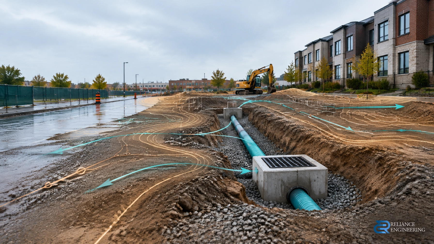
- Emergency overflow routes
- Direction of overland flow
- Protection of adjacent properties
This coordinated design prevents conflicts between the building layout, underground utilities, landscape areas, fire access, and stormwater facilities. It also gives contractors clear drawings and constructible routing.
Assess Major Overland Flow
The minor system handles runoff through catchbasins and storm sewers. The major system provides a safe route when the minor system is exceeded.
The assessment should confirm that larger storm events can move safely through the site without:
- Entering buildings
- Blocking emergency access
- Flowing onto adjacent properties
- Creating unsafe ponding near entrances
- Damaging retaining walls or foundations
- Bypassing the designed storage system
The overland route should be visible on the grading plan and supported by spot elevations, flow arrows, and sections where required. A defined emergency overflow is especially important for underground systems and surface storage areas.
Understand the Difference Between an FSR and an SWM Report
A Functional Servicing Report evaluates whether the proposed development can be serviced by available infrastructure. It generally covers:
- Water demand
- Fire flow, where required
- Sanitary flow
- Storm servicing strategy
- Existing municipal infrastructure
- Capacity and connection constraints
- Required upgrades
- Proposed servicing approach
A Stormwater Management Report focuses on runoff control and drainage design. It generally covers:
- Pre- and post-development drainage
- Runoff coefficients
- Peak flow calculations
- Allowable release rates
- Quantity control storage
- Orifice and outlet sizing
- Water quality treatment
- Overland flow
- Adjacent property protection
- Operation and maintenance
Some applications require both documents. A townhouse development, commercial site, apartment building, or redevelopment with limited servicing capacity may need an FSR to prove infrastructure feasibility and an SWM report to prove that runoff will be controlled.
Reliance Engineering coordinates both documents with the civil drawings to provide practical designs, clear calculations, and approval support.
What Reviewers and Conservation Authorities Check
Municipal reviewers commonly check whether:
- The criteria are clearly identified
- Existing and proposed drainage areas are accurate
- The allowable release rate is supported
- Storage is adequate for required storms
- The outlet is sized and protected
- The storm connection is legal and constructible
- The major overland flow route is safe
- The drawings and reports agree
- Maintenance responsibilities are defined
Conservation Authorities may also review:
- Floodplain and wetland limits
- Watercourse setbacks
- Regulated areas
- Fill placement
- Erosion and sediment control
- Water balance
- Infiltration feasibility
- Downstream impacts
- Drainage before and after development
Municipal approval does not replace a Conservation Authority permit where one is required. These constraints should be reviewed early because they can affect grading, storage, outlet location, and the overall site layout.

Prepare a Clear, Review-Ready Submission
A strong stormwater management report for a constrained Ontario site should include:
- Design criteria and approvals matrix
- Existing and proposed drainage plans
- Runoff and peak flow calculations
- Allowable release rate analysis
- Stage-storage-discharge data
- Storage and outlet details
- Water quality and LID strategy
- Storm servicing and connection calculations
- Major overland flow assessment
- Adjacent property protection measures
- Construction erosion and sediment controls
- Operation and maintenance requirements
The objective is not to add unnecessary complexity. It is to provide clear calculations, practical controls, and a coordinated design that can be approved and built.
Request a Stormwater Consultation
If your Ontario infill or redevelopment site has limited space for stormwater controls, begin with the criteria, receiving system, and site constraints.
Contact Reliance Engineering for a consultation on your stormwater management report, site servicing plans, functional servicing report, and municipal approvals strategy.
Professional Credentials and Contact Information
Naresh Ochani, P.Eng. M.Eng.
Principal Engineer
PEO Certificate of Authorization: 100548882
Reliance Engineering
6850 Millcreek Dr, Mississauga, ON L5N 2H4
Phone: 647-385-6418
Email: [email protected]
Office hours: Saturday 12:00 PM–2:00 PM; Sunday Closed
Request a consultation for practical stormwater controls, clear drawings, and responsive approval support across Ontario.
Technical References
- Ontario Stormwater Management Planning and Design Manual
- Ontario guidance for infill development
- Ontario Site Plan Control Guide
- Conservation Halton Stormwater Management Engineering Submission Guidelines
- Conservation Authority requirements under O. Reg. 41/24
- Reliance Engineering Stormwater Management Reports
- Reliance Engineering Site Servicing Plans
- Reliance Engineering Functional Servicing Reports