Category: Ontario Site Servicing & Stormwater
Date: October 28, 2026
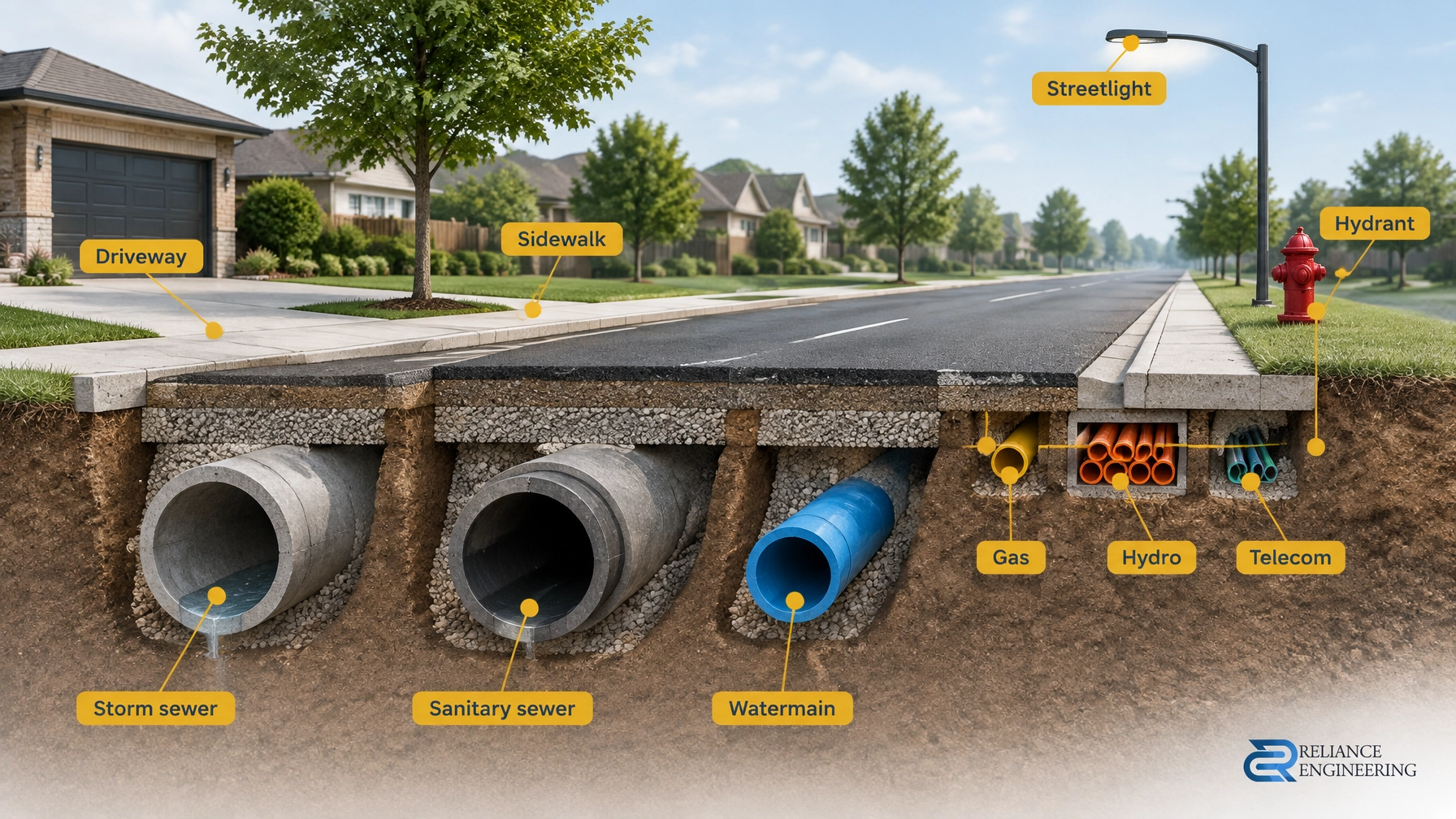
A site servicing plan may appear to own three pipe systems: water, sanitary and storm. But those pipes share a road allowance with gas, hydro, telecom, streetlighting, street trees, driveways and street furniture.
The most disruptive utility conflicts are often discovered after excavation begins. Avoiding them is a design-stage task. Clear drawings and coordinated design help identify conflicts while routes can still be adjusted on paper.
Coordinate deep and shallow utilities together
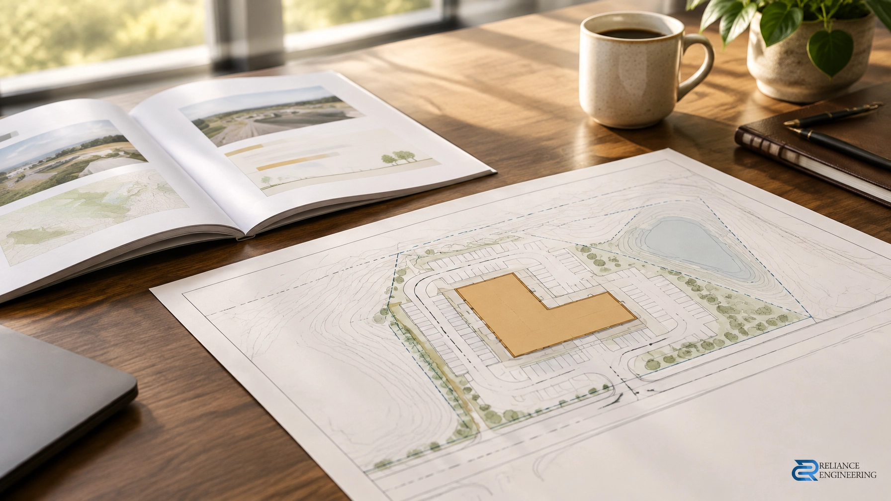
The servicing plan establishes routes for water, sanitary and storm. A Composite Utility Plan (CUP) brings those routes together with shallow utilities and surface features. It is the coordination drawing used to check whether pipes, utility structures, trees, driveways and other elements can fit in the same corridor.

A CUP is not simply a utility overlay. It records routes, structures, offsets, easements and other constraints that affect constructible routing. Municipal experience matters because the drawing must respond to the specific municipality’s criteria and utility-owner reviews.
Start with the provincial sewer–watermain separation guidance
Ontario’s MECP Procedure F-6-1, updated in July 2021, provides the provincial guideline backdrop for watermain and sewer separation. Municipal criteria build on this guidance, and project teams should confirm current local requirements.
For parallel installations, F-6-1 says watermains and sewers should generally be in separate trenches, with at least 2.5 m clear horizontal separation measured between nearest edges. The procedure defines sewers to include both sanitary and storm sewers, as well as forcemains.
Where unusual conditions (such as rock, severe dewatering problems or utility congestion) prevent that separation, F-6-1 describes a fallback: the sewer crown should be at least 0.5 m below the watermain invert, with in-situ material or compacted backfill between them. If that vertical separation cannot be achieved, the sewer must use materials and joints equivalent to watermain construction standards and be pressure tested under OPSS Division 701 at 350 kPa, with no leakage. These figures and conditions are from F-6-1; municipal criteria and approvals may vary.
At crossings, the procedure says the watermain should normally cross above the sewer, with enough vertical space for bedding and structural support. If the watermain must pass beneath a sewer, F-6-1 specifies at least 0.5 m between the sewer invert and watermain crown, adequate sewer support, and a water pipe length centred at the crossing so its joints are equidistant and as far as possible from the sewer.
F-6-1 also states that a watermain or service line must never pass through or contact a sewer, sewer manhole, septic tank or tile field. Water-system chambers must not connect directly to sanitary sewers, and blow-offs or air-relief valves must not connect directly to any sewer. The procedure specifies at least 15 m between sewers, drains and similar contamination sources and below-ground potable water reservoirs or well supplies. These are provincial guideline provisions; confirm the applicable municipal criteria for the project.

Municipal criteria turn coordination into a drawing requirement
The City of Markham’s Engineering Department Section G, Composite Utility Plans and Pavement Marking & Signage Plans, January 2024, Rev. 2, assigns the Consulting Engineer responsibility for preparing a CUP to avoid conflicts among utilities, street trees, municipal services and driveways.
Markham’s CUP requirements call for a 1:500 plan showing storm and sanitary sewers, catchbasins, maintenance holes, watermains and appurtenances, utility routes, above-ground structures, easements, driveways, trees, fences and retaining walls. Typical street cross-sections must show trench widths, depths and offsets.
The Markham document gives project teams practical examples of what that coordination can uncover. Its CUP notes specify that underground hydro must clear maintenance holes, catchbasins, valve chambers and hydrants by at least 1.2 m, or require concrete encasement; hydro lines are to be on the lot side of the hydrant with at least 0.6 m clearance; and gas mains must clear underground structures by at least 300 mm. The same document specifies 1.2 m clearance between street furniture and driveways and hydrants, and says utility road crossings must not occur at driveways. These are Markham-specific examples, not province-wide standards; confirm current criteria with the applicable municipality and utility owners.
The driveway detail is especially important. Markham requires water service connections to avoid future driveways and states that the builder is responsible for relocating a service connection if a conflict occurs. Designing around the future driveway is more practical than leaving the conflict for construction to resolve.
Markham also sets a clear review gate: the first CUP submission is due no later than the second detailed engineering submission. Each utility company must sign the completed CUP before the City signs it. Markham requires the engineer to approach utilities for sign-off even if they are not participating at that time.
Ottawa’s engineering specifications for planning applications show the same coordination pattern in another Ontario municipality. Ottawa’s subdivision CUP requirements include utility routes and service drops, streetlighting, street furniture, mailboxes, driveways and their clearances, easements, typical utility road cross-sections and lot servicing details. Ottawa specifies a metric plan scale of 1:500 or 1:250. These scales and requirements are Ottawa’s; confirm the applicable municipal submission standard for each project.
Records are a starting point, not confirmation
Utility records help establish a preliminary layout, but records-based information is not the same as a verified field location. Toronto’s Design Criteria for Sewers and Watermains, Third Edition, July 2026, encourages subsurface utility engineering (SUE) where underground information is insufficient or utility congestion is present. It references ASCE 38-22 quality levels, progressing from records and oral recollections (Level D), through surveyed visible features and geophysical detection (Levels C and B), to exposed utilities with precise horizontal and vertical measurements (Level A).
Where uncertainty or congestion could affect routing, SUE investigation or test pits can inform design before construction. Finding a conflict in a test pit allows the team to assess it before the main excavation is underway.
Toronto’s criteria also reinforce the importance of easements and routing in public rights-of-way. Easements should be identified and dimensioned as part of the coordination conversation, rather than treated as a later documentation step.
Ontario’s Underground Infrastructure Notification System Act, 2012 sets out locate obligations before excavation. Design-stage coordination should not rely on fresh paint on the ground: excavation locates are not a substitute for resolving proposed routes on the CUP and through utility review. Confirm field locations through the appropriate process before digging.
What this means for the site servicing plan
Plan water, sanitary and storm routes with separation in mind. Use the 2.5 m separate-trench approach described in MECP Procedure F-6-1 as the starting point, then document any applicable fallback where space is constrained. Reserve corridors for gas, hydro and telecom using the municipality’s cross-section and utility-owner criteria.
Keep proposed services clear of future driveways and avoid utility road crossings at driveways where the local criteria require it. Show easements, utility offsets and above-ground structures. Coordinate the routes with grading and stormwater management: catchbasins, maintenance holes, street trees, lighting and other structures all compete for space. A functional servicing report and stormwater management reports in Ontario should be considered alongside the site servicing layout where the project scope calls for them.
Treat utility sign-off as a gate in the drawing cycle, not a rubber stamp.
Pre-submission utility coordination check
Before submitting, confirm that:
- Municipal engineering standards and the applicable utility cross-section are confirmed.
- Separation logic is shown, including the F-6-1 fallback where required.
- The CUP is circulated to every utility, including non-participating utilities where required, with signature blocks.
- Services are routed clear of future driveways and utility road crossings are kept away from driveways where required.
- Utility easements are identified and dimensioned.
- SUE investigation or test pits are planned where records are old, sparse or the corridor is congested.
A servicing plan is judged not only by slopes and inverts, but by whether every other system that must share the corridor fits around it. Reliance Engineering provides practical designs, clear drawings and approval support for site servicing plans across Ontario.
Request a Consultation to review servicing routes and utility coordination before drawings go in.
Contact and Professional Credentials
Naresh Ochani, P.Eng., M.Eng.
Principal Engineer
Reliance Engineering Canada Limited
PEO Certificate of Authorization: 100548882
6850 Millcreek Dr, Mississauga, ON L5N 2H4
647-385-6418
[email protected]
Office hours: Monday–Friday 9:00 AM–5:00 PM; Saturday 12:00 PM–2:00 PM; Sunday Closed.