Article type: Technical how-to and municipal review checklist
Focus: Ontario site servicing plans, stormwater management reports, and functional servicing reports
Published: September 24, 2026
Service area: Ontario-wide
Storm sewer connections are often reviewed as part of a larger civil package. Municipal engineering staff are not only checking whether a pipe reaches the municipal system. They are checking capacity, inlet performance, elevations, cover, conflicts, outfall safety, stormwater controls, and the relationship between the minor and major drainage systems.
A storm connection that is shown clearly, supported by calculations, and coordinated with grading and other utilities is easier to review and construct.
The requirements vary by municipality, watershed, and project type. The Ontario Stormwater Management Planning and Design Manual provides a provincial framework, while local municipal standards and Conservation Authority criteria control many project-specific details.
1. Size catchbasins and inlets from actual drainage conditions
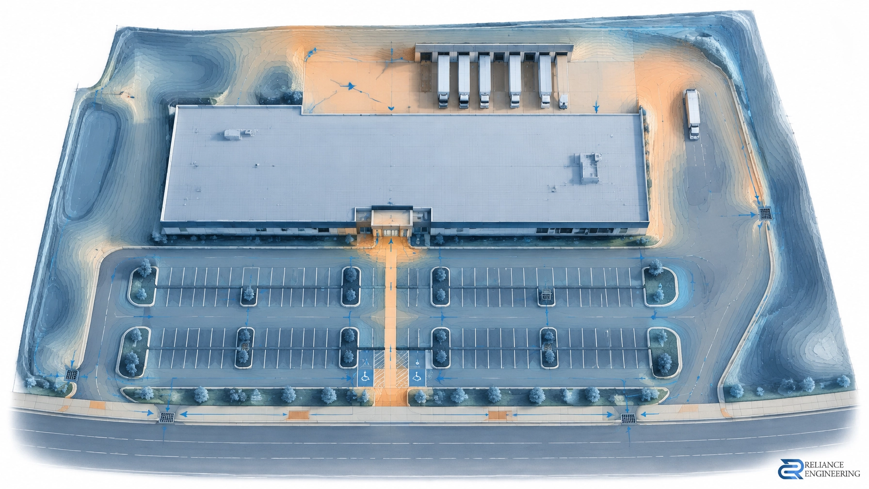
Catchbasin locations should follow the proposed grading plan, not simply a standard spacing assumption.
Inlets are typically placed at:
- Road and parking lot low points
- Changes in grade
- Intersections and sag locations
- The start and end of gutter runs
- Locations where overland drainage enters the minor system
- Areas where ponding could affect building entrances or accessible routes
There is no single catchbasin spacing requirement that applies across Ontario. Spacing depends on gutter flow, inlet capacity, road crossfall, longitudinal slope, contributing area, design storm, and the applicable municipal standard.
For road systems, the design should demonstrate that the proposed inlet arrangement captures the required minor system flow without excessive bypass or gutter spread. For private sites, the calculations should show that parking areas, drive aisles, loading areas, and accessible routes drain safely to the proposed inlets.
Catchbasin leads also require municipal review. Common criteria may distinguish between single and double catchbasins, with different minimum pipe diameters and slopes. The correct size must be confirmed against the municipality’s current engineering standards rather than copied from a general detail.
A clean layout should identify:
- Catchbasin type and number
- Lead diameter and slope
- Direction of flow
- Sump or outlet connection
- Maintenance hole connection
- Finished grate elevation
- Pipe invert elevation
- Any inlet control device or restrictor

2. Demonstrate storm sewer capacity and slope
Storm sewer sizing normally begins with the contributing drainage area and the selected design storm. Depending on the site and municipality, the analysis may use the Rational Method, a hydrologic model, or a combination of methods.
The design should establish:
- The drainage area contributing to each pipe section
- The runoff coefficient or other hydrologic parameters
- The design rainfall intensity
- The calculated peak flow
- Pipe diameter, material, slope, and roughness
- Full-flow capacity and velocity
- Hydraulic grade line, where required
- Connection capacity at the municipal system
Municipal standards commonly set minimum storm sewer diameters to reduce sediment accumulation and maintenance problems. The Ontario manual identifies approximately 250 mm as a general minimum for storm sewers, but several municipalities require 300 mm or larger. The local standard controls.
Pipe slopes must be practical and constructible. A steep pipe may create high outlet velocities or conflict with downstream grades. A flat pipe may create sedimentation, surcharge, or difficult construction conditions. The design should balance capacity, self-cleansing performance, cover, connection elevations, and the available outlet.
A site servicing plan should not only label pipe sizes. It should make the hydraulic logic easy to follow. This is where clear drawings, clear calculations, and municipal experience reduce review comments.
3. Show minimum cover and protect the pipe system
Cover is measured from finished grade to the top of the pipe, also called the obvert. The required cover depends on the municipality, pipe material, loading condition, location, frost protection, and whether the pipe is in a road, parking area, boulevard, or landscaped area.
Ontario guidance commonly identifies approximately 0.9 m of cover where the sewer is not in rock, while some municipal standards require 1.2 m or more. These values are not interchangeable. The applicable municipal standard should be identified in the design notes.
Where minimum cover cannot be achieved, the submission may require:
- Structural calculations
- Higher pipe strength or a different pipe class
- Concrete encasement
- Insulation
- Adjusted finished grades
- A revised servicing route
- Municipal approval for a variance or special condition
Cover must be checked against the final grading design. A storm sewer that meets cover requirements on an early concept plan may fail after ramps, curbs, parking grades, retaining walls, or building elevations are finalized.
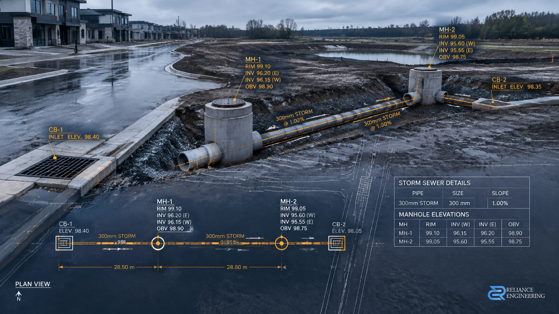
4. Coordinate invert, obvert, and maintenance hole elevations
Elevation errors are a common cause of municipal comments and construction changes.
For each storm sewer section, the drawing should identify the upstream and downstream inverts, pipe slope, pipe diameter, and maintenance hole elevations. The obvert can be checked from the invert and internal pipe diameter:
Obvert elevation = invert elevation + internal pipe diameter
The design must also confirm that the downstream pipe is hydraulically lower than the upstream connection. At maintenance holes, the inlet and outlet obverts should be coordinated so the system does not create an unintended hydraulic obstruction.
Show the following where applicable:
- Invert elevation at each pipe connection
- Obvert elevation where required
- Top of grate elevation
- Maintenance hole rim elevation
- Pipe diameter and material
- Drop structure or internal drop detail
- Hydraulic grade line
- Basement or lowest building opening elevation
- Freeboard to the relevant hydraulic grade line
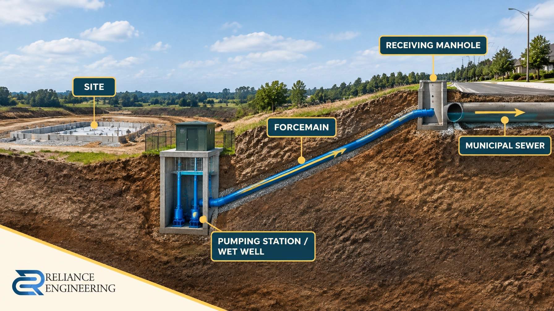
The design should also check whether the municipal system can accept the proposed connection. A private storm sewer can have adequate local capacity while the downstream municipal sewer is already constrained.
5. Coordinate storm, sanitary, and water services before finalizing the route
Storm, sanitary, and water services should be designed together. Separate plans that are not coordinated can create conflicts at crossings, maintenance holes, building entrances, and municipal road connections.
The coordinated design should review:
- Vertical separation between services
- Horizontal clearances
- Crossing locations
- Watermain and sanitary sewer conflicts
- Utility easements
- Hydro, gas, and telecommunications
- Building foundation elevations
- Fire access and hydrant locations
- Landscaping and tree protection zones
- Construction access and excavation limits
Constructible routing is particularly important on constrained infill, commercial, and townhouse sites. A route that works in plan view may not work when cover, trench width, shoring, bedding, and utility clearances are considered.
Reliance Engineering prepares Site Servicing Plans that coordinate storm, sanitary, water, grading, stormwater management, and municipal connection requirements.
6. Document storage, orifice controls, and tie-ins
Many Ontario developments cannot discharge unrestricted post-development runoff to the municipal system or a receiving watercourse. The allowable release rate is project-specific and may be based on:
- Existing downstream sewer capacity
- Pre-development peak flow
- Watershed or subwatershed studies
- Municipal stormwater criteria
- Conservation Authority requirements
- Erosion thresholds
- Flood protection objectives
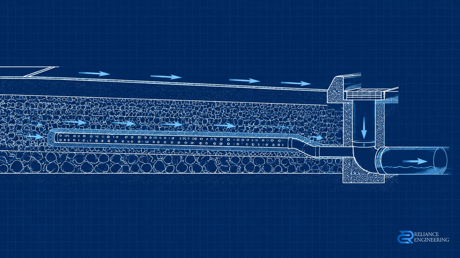
Storage may be provided in a stormwater management pond, underground tank, oversized pipe system, parking lot, rooftop system, or other approved control.
An orifice, restrictor, inlet control device, or outlet tube must be shown as a complete system. The submission should identify:
- Storage volume
- Controlled release rate
- Control device size and type
- Upstream and downstream inverts
- Emergency overflow
- Maintenance access
- Stage-storage-discharge relationship
- Drawdown time
- Blockage or freezing considerations
A practical control is one that can be inspected, maintained, and protected from accidental removal. The control should also be coordinated with the site grading plan so water remains away from building openings during the design event.
Reliance Engineering’s Stormwater Management Reports include pre- and post-development runoff analysis, allowable release rate calculations, quantity control storage, orifice sizing, overland flow assessment, and water quality considerations.

7. Design the outfall as part of the approval package
The outfall is not a drafting detail to be added at the end. It is the final hydraulic connection between the site and the receiving system.
Outfall drawings should show:
- Pipe size, material, slope, and invert
- Headwall, wingwalls, or outlet structure
- Receiving channel or municipal system
- Riprap or other erosion protection
- Energy dissipation measures
- Bank and channel stability
- Tailwater conditions
- Access for inspection and maintenance
- Release rate and design flow
- Regulatory or flood elevations where applicable
Where a storm sewer discharges to a natural watercourse, the outlet velocity must be assessed. High or supercritical velocities may require riprap, a stilling basin, plunge pool, level spreader, or another engineered energy dissipation measure.
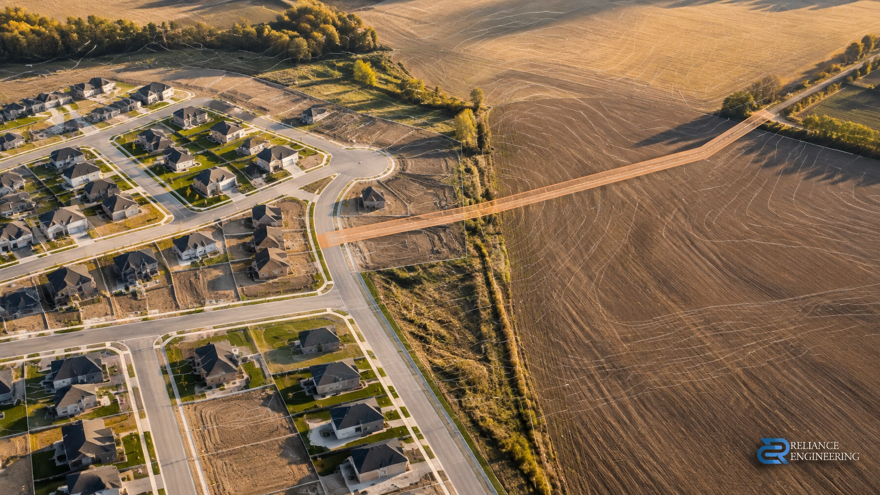
The outfall should also be reviewed for submergence during high water levels. Conservation Authority criteria may require the outlet invert to remain above a specified flood elevation or bankfull condition. The final requirement depends on the receiving system and applicable watershed policy.
8. Use a Functional Servicing Report to prove capacity
A storm connection on a servicing plan shows the proposed infrastructure. A Functional Servicing Report explains whether the overall development can be supported.
For storm servicing, the report should address:
- Existing municipal infrastructure
- Existing and proposed drainage areas
- Storm sewer connection points
- Downstream capacity
- Pre- and post-development flows
- Stormwater storage and controls
- Overland flow routes
- Major and minor system performance
- Outfall and receiving system conditions
- Required upgrades or restrictions
This evidence is especially important for site plan control submissions, OPA/ZBA applications, subdivisions, commercial developments, and projects near constrained municipal systems.
A report that only states “the site will connect to the existing storm sewer” is unlikely to provide sufficient approval support. Reviewers need clear calculations, a coordinated design, and practical conclusions.

9. Confirm Conservation Authority and MECP requirements early
A Conservation Authority review may be required where a project is near or within a regulated watercourse, wetland, valley, floodplain, erosion hazard, or other regulated feature. The Authority may review:
- Floodplain and hydraulic impacts
- Watercourse setbacks
- Outfall location
- Erosion protection
- Flood and erosion control
- Water quality and temperature
- Major overland flow
- Construction erosion and sediment control
- Fill placement and grading changes
MECP-driven requirements may also enter the project where environmental approvals, sewage works, receiving water impacts, groundwater protection, or other regulated matters apply. The appropriate requirements should be confirmed during pre-consultation with the municipality and relevant agencies.
Reliance Engineering prepares coordinated stormwater management, erosion and sediment control, grading, servicing, and approval documentation for development projects across Ontario.
Municipal review checklist
Before submission, confirm that the package includes:
- Catchbasin and inlet locations supported by grading
- Catchbasin spacing and inlet capacity checks
- Pipe sizes, slopes, materials, and design flows
- Minimum cover verification
- Invert, obvert, and grate elevations
- Maintenance hole connection details
- Storm, sanitary, water, and utility coordination
- Storage and outlet control calculations
- Allowable release rate confirmation
- Overland flow route
- Outfall and erosion protection details
- Functional servicing conclusions
- Municipal, Conservation Authority, and applicable provincial criteria
Request a storm servicing consultation
Need storm sewer connections, site servicing plans, stormwater management reports, or approval support for an Ontario development project? Contact Reliance Engineering for a consultation before your first municipal submission.
Contact and Professional Credentials
Reliance Engineering
6850 Millcreek Dr, Mississauga, ON L5N 2H4
Phone: 647-385-6418
Email: [email protected]
Office hours: Monday to Friday 9:00 AM–5:00 PM; Saturday 12:00 PM–2:00 PM; Sunday Closed
Naresh Ochani, P.Eng. M.Eng.
PEO Certificate of Authorization: 100548882